|
Canada, as befits a new and great country, has always
been prompt to utilize new engineering and scientific developments, and in no
field has this been more marked than in the way in which our government and our
people have made use of the art of wireless, — or, as it has later become
termed, radio communications — and without detracting in the slightest degree
from the work of Marconi, in first conceiving the idea of using Hertzian waves
for the purpose of communication, and then in developing the apparatus to attain
this end, the importance of the contributions to the radio art, of that
brilliant Canadian engineer, Reginald A. Fessenden, born at Milton, Ontario, are
becoming more appreciated as the years go by, and it is a fitting tribute to Mr.
Fessenden that within the last few months he has been chosen by the American
Museum of Safety as the recipient of the "Scientific American" Medal for his
contributions to the "Safety of Life at Sea."
Canada's first adventure into radio communication
took place 29 years ago when in 1901, the late Mr. D. H. Keeley, a member of
this Institute and Superintendent of the Government Telegraphs, entered into a
contract with Mr. Marconi to establish two stations in the Belle Isle Straits,
one at Chateau bay at the terminus of the landline on the mainland, and the
other on Belle Isle, thirty miles distant, to replace the submarine cable which
was continually going out of commission on account of icebergs.
It is a far cry from the thirty mile station of 1901,
to the 10,000 mile station of today, but it was a still farther cry from nothing
at all to 30 miles, and the promptitude with which Mr. Keeley seized on this new
means of communication, at such an early date, to solve his difficulties,
indicates that he, in common with so many of the founders of our Institute,
possessed the true spirit of the pioneer. fn fact not only did Mr. Keeley make
the contract, but he personally contributed to the success of the experiment. In
his report of November 1901, he naively states: "This Chateau bay installation
was in readiness on Sunday the 20th October, when signals from Chateau bay were
received at Belle Isle, but none were received at Chateau bay. The trouble, on
investigation, was attributed to defective coherers, and the company's agents
proposed abandoning the plant till next year in the absence of a fresh supply.
On the 22nd, however, I personally succeeded in establishing communication and
was thereby enabled to avert the threatened postponement of operations; and on
the 25th, after considerable practice and careful directions, for all that the
working of the system as it stands is erratic, I felt confident in leaving our
operators in charge, with the explicit instruction as to future action."
'While in this experiment, wireless telegraphy
demonstrated its utility to replace a cable, it was in an allied field that it
made its greatest contribution to progress and to the safety of human life, in
providing the first means for communicating with a ship at sea, and accustomed
as we are today to a condition where a ship is never out of communication
wherever she may be in the world, it is difficult to appreciate, for instance
that only a few years prior to the invention of wireless, the
S.S. Borussia left Liverpool, with 344 souls aboard, sprang a leak in mid
Atlantic and foundered; 160 persons went down on the ship, and 184 took to the
boats of whom only 10 were eventually saved. It is of interest to note that the
Marconi Company's records show that the first commercial equipment on board a
liner was installed in 1901 on the Beaver Liner "Lake Champlain" plying from
Liverpool to Montreal.
Those who heard Marconi during his trans-Atlantic
broadcast a few weeks ago, will recall that the first trans-Atlantic signals
were received at St. John's, Nfld., by means of an aerial supported by a kite
on December 12th, 1901, and Sir Wilfrid Laurier, the Canadian Prime Minister,
then in power, quick to appreciate the possibilities of wireless, invited the
young inventor to proceed to Canada, with the result that a contract was
entered into for the establishment of a transatlantic wireless service between
Canada and Great Britain, the Canadian Government to pay a subsidy of $80,000
towards the Canadian stations.
Glace Bay, N.S., was selected as the site, and in
1902 the first messages were exchanged between the Earl of Minto, then
Governor General of Canada, and His Majesty King Edward VII. After a somewhat
prolonged experimental period, the first commercial trans-Atlantic service—in
fact the first long distance service in the world — was inaugurated between
the station at Glace Bay and one in Clifden, Ireland, in October, 1907, and it
might here be added that the inauguration of this service contributed to the
fact that we are today paying a toll of only 18 cents per word on our
trans-Atlantic messages, as compared with 25 cents per word, the rate
previously in effect.
Concurrently with the contract for the
establishment of the first Glace Bay trans-Atlantic station, contracts were
entered into for the building of a chain of twenty coast stations along the
river and Gulf of St. Lawrence, to the Belle Isle Straits and from St. John
and Halifax to Cape Race along the east coast. These stations were of
comparatively low power and were installed in 1903, 1904 and 1905, and it is
a tribute to the quality of the apparatus that at some of these stations in
the more isolated points, where they do not cause interference, the major part
of the original plant, is still in operation.
In 1907 work was started on a chain of 9 stations
to provide communication along the coast of British Columbia, including the
Queen Charlotte Islands, and in 1912 a third chain of eight stations was
established from Port Arthur to cover the Great Lakes, incidentally linking up
with the east coast chain at Montreal.
At all these stations constant watch was
maintained, day and night, 365 days a year, or throughout the season of
navigation, as the case might be, and from the time a ship was 250 miles from
our shores she was in constant touch with one or other of the stations until
she reached her final port.
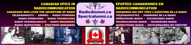
The original stations all carried about the same
plant, the prime mover was a 4 h.p. engine and the transmitter was of the
spark type rated at 2 k.w. At first coherers, and shortly afterwards magnetic
detectors (the latter due to the research work of Dr. Rutherford of McGill
University), were used for reception, and the working range of this
combination was some 250 miles.
As the art progressed, higher powered and more
efficient sets using the same type of transmitter of 5 k.w rating replaced the
original outfits, and with the more sensitive crystal type of detector the
range of the stations was materially improved. Nevertheless the general
design remained fundamentally unchanged, except in minor details. until the year
1918, when transmitters employing the vacuum tube began to be universally
adopted.
|
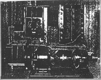
Figure No. 1
Spark Type of Transmitting Apparatus Originally
installed at Station on the Great Lakes |
Prior to this, radio engineers had long recognized
that damped Hertzian waves, such as are created by an electric discharge across
a spark gap, were by no means ideal for wireless communication. Such
transmission occupies a broad band in the ether and its carrying powers are
limited.
It is believed that the first practical method of
producing a pure continuous wave was due to Dr. Fessenden, when in 1908, he
built a high speed alternator making 20,000 revolutions per minute, which gave a
frequency of 100,000 cycles. (3000 metres.)
The frequency of an alternator is, of course, a
function of the speed, and as there are physical limitations to the latter, it,
was not found practicable to develop an alternator which would produce electric
waves of the frequencies then used for ship to shore communication of the order
of 1,000,000 cycles per second. (300 metres.)
For long wave long-range work, however, the
alternator was a success, and the General Electric Company developed machines
capable of an output of 200 k.w. with frequencies of the order of 30,000 cycles
(10,000 metres) which were extensively used for trans-atlantic and other long
distance services.
It may be remarked that it was whilst experimenting
with these continuous waves that Fessenden contributed his principle of
heterodyne reception to the radio art, —a principle simple but eminently
effective, and one which is used for reception at all continuous wave
radio-telegraph stations today.
Marconi endeavoured to obtain continuous waves by
means of a timed spark arrangement, while Poulsen made use of the negative
characteristic of an arc in hydrogen. Prior to the war, a large trans-atlantic
station of the latter type was built in Canada at Newcastle, N.B., and two or
three smaller sets were installed by the Marine Department in coast stations.
However, these were all temporary expedients waiting for the development of the
vacuum tube, and such of them as are still in existence, will, together with the
alternators, ere long be relegated to the historical museum along with the spark
sets and be replaced by the three element vacuum tube.
This tube is due to the work of Dr. Lee DeForest of
New York, who in 1907, experimenting with the two element vacuum tube detector
developed by Fleming, conceived the idea of introducing a third element into the
tube, which he called the grid, and thereby he made possible the present
phenomenal development in radio, though it is doubtful whether at that time
DeForest had the slightest idea of the revolution he was about to inaugurate.
It may perhaps seem strange that this tube can be
used both for reception and transmission. However, every one who owns a radio
broadcast receiving set probably has a nightly demonstration of the latter, when
the owner of a neighbouring one tube regenerative set proceeds to whistle
through his concert. He is using his receiving tube as a transmitter and it is
made audible to the receiving set through Fessenden's heterodyning effect. In a
large transmitting station there is merely a repetition on a large scale of what
goes on in the one tube regenerative set. With a vacuum tube transmitter it is
possible to produce a pure continuous wave and at the same time to control it
when using high power. As compared with a damped wave a continuous wave travels
a much greater distance for the same expenditure of energy, occupies a very much
narrower band in the ether and when modulated with a microphone it enables us to
transmit sounds at voice frequencies.
The large investment in Canada and througout the
world in ship-to-shore spark equipments delayed the early adoption of the tube
type of transmitter, but insofar as Canada is concerned, the advent of
broadcasting rendered such a change urgently desirable in the interest of
broadcast listeners, and the Canadian Marconi Co. having, on our behalf,
developed a tube transmitter suitable for coast station operation, the
government embarked on a pro-gramme of replacing all spark sets in its stations,
commencing with those in the more populous centres such as Toronto, Montreal,
Vancouver, etc., with the result that today, except in one or two isolated
points, all our stations are operating on continuous wave.
This transmitter is rated at 1600 watts output and
has a frequency range of 500 to 100 kilocycles. For convenience in handling, it
is divided into five units, viz., rectifier, oscillator, closed circuit
inductance, closed circuit con-denser, and aerial tuning inductance. The
components of each unit, are mounted on angle iron frames which are covered with
wire mesh screens to prevent accidental contact with high voltage conductors.
All high voltage parts are insulated with porcelain. Power is supplied to the
set at. 220 volts 60 cycles. This is stepped up to 20,000 volts, and double wave
rectification is carried out by two rectifier tubes. The resultant direct
current at 10,000 volts, after being passed through a filter. fed to the anodes
of two oscillator tubes operating in parallel in a Hartley circuit. Small
transformers of suitable ratio supply current for heating the filaments of the
oscillator and rectifier tubes. The condenser in the closed circuit, is
insulated with porcelain and uses air as the dielectric in order to avoid
possible trouble which might result from failure of a solid dielectric such as
mica. The aerial tuning inductance is coupled to the closed circuit by means of
an aperiodic link and both the closed and aerial tuning units are equipped with
selector switches for quickly changing to any one of four predetermined waves.
Interrupted continuous wave trans-mission is obtained by means of a motor driven
tonic train wheel and the set is also equipped with a small low voltage motor
generator for supplying direct current to operate the keying relay and magnetic
send-receive switch.
The keying relay interrupts the primary of the power
transformer of the rectifier and also a fraction of a second afterwards a second contact interrupts the grid
circuit of the oscillator tubes. This is necessary in order that the
morse characters transmitted should be sharply defined.
The transmitter is completely controlled from the
operator's desk.
For ships, sets of a smaller and more compact type
were developed, and those standardized in Canada are the 500-watt continuous
wave and interrupted continuous wave transmitter and the 100-watt continuous
wave, interrupted continuous wave and telephone transmitter, short descriptions
of which follow:
The 500-watt ship equipment is a one-unit set
delivering 500-watts of high frequency energy to the antenna. It consists of a
rigid angle iron frame upon which are assembled the component parts of the
oscillatory and control circuits. Continuous wave and tonic train communication
are provided over the wave range of the transmitter, and either method of
signalling is available by throwing the signal switch mounted on the transmitter
panel.
|
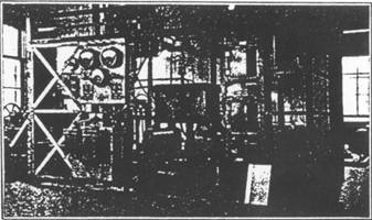
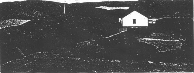
Figure No. 2
25-Kilowatt Poulsen Arc Transmitter installed at
Barrington, N.S. - Now Obsolescent |
In laying out the transmitter, attention has been
paid to the special requirements of ship use. The overall size of the unit is
such that it will pass through the ordinary ship's cabin door. All vital parts
of this transmitter are clear of the floor.
The transmitter has a wave range of from 600 to 2,400
metres (500 to 125 kilocycles) when used with an aerial having a natural
wavelength of 250 metres, and a capacity of .0007 microfarad. Any one of four
wavelengths in this range may be selected by a single operation switch. The
transmitter is normally wired to permit of two wave-lengths in the bands from
600 to 1,300 metres and two in the band from 1,200 to 2,400 metres.
A 2,000 volt d.c. generator, rated at. 1,500 watts
output and direct connected to a 110-volt d.c. motor, supplies the high tension
power for the oscillator valves. This machine is provided with an automatic
starter controlled by a push button switch from any convenient place. Provision
is also made for opening the generator field circuit when receiving.
A low voltage generator, driven by a 110-volt d.c.
motor supplies the heating current for the valve filaments.
The power supply for both motors is drawn from the
110-volt ship's mains. The two machines are independent of the transmitter and
may be placed where convenient.
The insulation of the transmitter has been given
careful consideration and is designed for an ample safety factor as regards
creepage and flash over.
The 100-watt transmitter provides three classes of
radio transmission, namely, radiotelephony, continuous wave and interrupted
continuous wave telegraphy. It is capable of deliverying 100 watts to the antenna
when used for telephony or interrupted continuous wave and 150 watts when used
for continuous wave signalling.
|
Figure No. 3
1,600-Watt C.W. and I.C.W. Transmitter used
at Canadian Coast Stations |
The apparatus is ruggedly constructed and is simple
to install and operate. Protection to both operator and apparatus is afforded
by the necessary screening, fuses, by-pass condensers, etc.
The complete equipment consists of transmitter
unit, high and low tension motor-generator unit and associated control
rheostat, power control switches, signalling key and microphone equipment.
The power equipment consists of a motor driving a
double current generator supplying 1,000 volts d.c. to the valve anodes and 12
volts 12 amperes for the valve filaments and auxiliary equipment such as the
tone wheel motor and high tension magnetic switch energizing coil. Switches
are provided for the line voltage, and a control rheostat for the regulation
of the generator field current.
The wavelength range of the transmitter is between
200 and 800 metres, (1,500 and 375 kilocycles) depending on the aerial
dimensions. A wave-change switch is provided which permits the quick selection
of any one of three fixed wavelengths within the wavelength band.
The oscillatory circuit is of the Hartley type
excited by one UV-211 Radiotron modulated by a second UV-211 in the so-called
constant current circuit. The microphone circuit is transformer coupled to the
modulator valve. For continuous wave communication both valves are used as
oscillators, a switching arrangement enabling this to be carried out.
Tonic train transmission is obtained by connecting
a small motor and tone wheel with signalling key to the modulation transformer
in place of the microphone.
Before being fed to the speech choke, the high
tension supply passes through a filter which effectively suppresses the
generator commutator ripple.
MODERN TENDENCIES IN "SHIP TO SHORE" TRAFFIC
For revenue the ship-to-shore stations look to
traffic from ships, and in the early days, when ships could only work some two
or three hundred miles, stations such as Cape Race and Belle Isle were of
great importance and good revenue producers. For instance, the revenue from Cape
Race for the year 1920 was $82,000.00. Last year, however, the revenue from this
same station was only $1.500.00, this being due to the fact that traffic can be
much more effectively handled through a central station located at a point with
good telegraphic facilities. On the east coast of Canada this service is
provided by the Canadian Marconi Company's commercial station at Louis-burg, N.S.,
and on the west coast by the departmental station at Estevan.
Even this arrangement is in a state of flux, as ships
are now all turning towards short waves and it may well be that in the near
future we will find the traffic going to short wave long distance stations
situated at terminal points such as Montreal. Looking towards this end, the
Marine Department has just commenced construction on an up-to-date radio station
outside of Vancouver, B.C., which, equipped with long waves, intermediate waves
and short waves, will be in a position to handle all traffic offering.
The cost and range of this station, as compared with
that of the first one on Belle Isle, indicate the growth and change which have
taken place. The contract price for Belle Isle complete with buildings was
$5,000 and it had a range of about 50 miles. The station at Vancouver will cost
$100,000 and on the short wave we expect to be able to take care of traffic from
ships as soon as they have left Sydney, Australia, or Singapore, as the case may
be.
RADIOTELEPHONE SERVICE
An interesting development inaugurated by the
Department on the Pacific Coast, in 1924, is a radiotelephone service to and
from tug boats and other small vessels plying on the Coast. Radio telephone
stations have been established at Vancouver, Merry Island, Cape Lazo, Alert Bay
and Digby Island, (see map), and the service has proved of great value to tug
owners, some forty-nine tugs being now equipped. This is purely a point-to-point
service, and has not as yet been extended to the regular land telephone lines.
The number of paid radio telephone calls handled by
these stations last year was 12,540.
POINT TO POINT COMMUNICATION
The chains of stations established by the government
on the east coast, Hudson Straits, etc., whilst established primarily for
ship-to-shore communication, serve a second useful purpose in providing
facilities for communication with small stations erected at isolated points by
private enterprise. On the Pacific coast, for instance, service is given to some
36 local stations located at canneries, pulp mills, etc., which have no access,
and, on account of the rugged nature of the country, are not likely to have
access to landline facilities for many years to come.
An example recently brought to the public eye was the
story of the MacAlpine expedition, which was handled through a small station
established by the Dominion Explorers at Bathurst Inlet, communicating with the
outside world through the Port Churchill station of our Hudson Bay chain.
|
Figure No. 5
500-Watt Ship Type Transmitter
developed in Canada |
Similar communication facilities are available to
isolated communities in the interior of Canada through the medium of the radio
stations operated by the Royal Canadian Corps of Signals along the McKenzie
river in the North West Territories and at several other points across Canada at
which that service maintains stations in connection with civil aviation
activities.
Point to point communication is also extensively used
by public utilities and power companies, for emergency in communication between
their power plants and distribution centres in case of interruption of the
normal telegraph or telephone communication, and an interesting experiment is
being undertaken at this moment by the British Columbia Telephone Co. at Powell
river, on the Pacific Coast, looking to the use of radio links in the
establishment of regular telephone service to isolated points. If this
experiment proves successful, a big development may be anticipated along these
lines, there being hundreds of places in Canada to which it is not economical,
up to the present, to extend regular telephone service, particularly in the case
of plants and communities located on islands.
The use of this phase of radio service by the
landline companies of Canada for emergency communication between their important
centres in case of interruption of their landlines is also foreshadowed in the
immediate future.
RADIO DIRECTION FINDING
The first use of radio at sea was simply to provide
communication, but as years progressed a development of major importance to
navigation took place in the application of radio to direction finding, whereby
it is possible to determine by means of special antennae and receiving apparatus
the direction or bearing of an incoming signal. The principles involved in
direction finding had been known for many years, but it required the invention
of the vacuum tube with the immensely improved sensitivity of reception secured
thereby to make it of utility as an aid to navigation.
Much work was done on this during the war, and the
first direction finding stations in Canada were four established on the east
coast in 1917, for war purposes. At the close of the war it was decided to
continue these stations as an experimental aid to navigation. They were so
successful that additional stations were established at Saint John, N.B., St.
Paul Island, Yarmouth, N.S., Belle Isle, on the East Coast, and Pachena on the
Pacific coast.
The Canadian direction finding stations give
approximately 38,000 bearings per annum, and while they are not intended to
supersede existing instruments of navigation they act as an accurate check.
Fixes are obtained by intersection of the bearings from two or more stations, or
a ship can navigate on a line of bearing, as for example, on approaching Saint
John up the Bay of Fundy. As an instance of how navigators regard this
comparatively new radio instrument, a letter may be quoted from the Captain of a
10,000 ton ship, which arrived in Halifax on December 31st last:
Port of Halifax, N.S.
January 10th, 1930
Department of Marine and Fisheries,
Radio Branch,
Halifax, N.S.
Dear Sirs:
In submitting to you a report on D.F. bearings
furnished by Chebucto and Canso Stations, the experience narrated hereafter may
be of interest.
Being bound from Glasgow to Halifax, and following
Track "E" of Atlantic Lane Routes, no position by celestial observation was
obtainable after our crossing Longitude 40 West on December 26th, 1929, and
recourse was had to W.T.D.F. bearings from C'ape Race, first being obtained at a
distance of 200 miles. From then onwards bearings were got at intervals and
these were checked by ship's D.F. apparatus working on the Newfoundland and
Sable Island Stations.
On December 30th a severe Southwesterly storm was
encountered, during which steamer had to be hove to, and in six hours was driven
30 miles South-South-east. Bearings from Chebucto and Canso Stations faithfully
recorded ship's retrogression.
After storm abated, relying entirely on position
obtained by Wireless,—whereabouts by "Dead Reckoning" being merely a guess- -a
course was set for Halifax Inner Fairway Buoy, at which we duly arrived on the morning
of December 31st. Indeed by carrying on long enough we should have collided with
the buoy.
I venture to suggest that the W.T.D.F. Stations named
could not be given a more severe test than under the circumstances recounted.
Here is a steamer navigated for practically 1,000
miles by W.T.D.F. alone, in a part of which distance and for a period of twelve
hours she is exposed to a severe storm and driven far out of her course, various
adjustments of courses steered are made as indicated necessary by D.F. bearings,
and arrives at her. destination not as much as a cable's length in error.
The writer respectfully commends to the attention of
the Department the unfailing courtesy. promptitude, zeal and care shown by the
Officers operating all Eastern Canadian Stations—D.F.—from Belle Isle to Redhead
(Saint. John).
Their dutifulness contributes in no small measure to
relieve the many anxieties of those "Toilers of the Deep" upon whom devolves the
safety of life and property afloat, numbered with the most appreciative of whom
is,
Yours faithfully,
......................... Master.
|
Figure No. 6
General View of the Canadian Direction
Finding Station at Saint John, N.B. |
Our latest application of direction finding as an aid
to navigation is in Hudson Straits and Hudson Bay, where radio may be said to
have truly come into its own. There are no lighthouses—there are no fog
alarms—and the magnetic compass is sluggish by virtue of proximity to the
magnetic pole.
It should not be understood, from the above, that
lighthouses or fog alarms have been superseded or will not be installed in these
waters in the near future. Nevertheless, it is a tribute to radio direction
finding that it was chosen as the most effective way of covering this long
stretch of some 1,000 miles as a preliminary measure.
Four stations of the latest type are now in operation
at Resolution Island, Hopes Advance, Nottingham Island and Churchill (see map)
and have been fully utilized by the ships plying in those waters. The stations
are manned the year round and provide a useful service in their weather
observations which are of great value to the Meteorological division of the
Department of Marine, in making up the daily weather forecasts. Communication
with the outside is maintained by by long wave communication between Resolution
Island and Father Point or Belle Isle on the St. Lawrence system, and also via
Port Churchill and the Canadian National land-line.
Those who are interested in the principle of
direction finding will note that when a receiver is connected to an ordinary
antenna a polar curve of reception is obtained in the form of a circle, that is
to say, the antenna receives with equal intensity from all directions. If
however, we substitute a loop antenna and move a transmitter around it through
360 degrees, we find that as the transmitter progresses around the loop, there
will be two definite positions 180 degrees apart where the received signal will
be of maximum strength, and two other positions 90 degrees from the former where
the signal will be at minimum strength.
|
Figure No. 7
Interior of the Operating Room
at the Canadian Direction Finding
Station at Saint John, N.B. |
Similar variations of signal strength will be
obtained if the transmitter is stationary and the loop is revolved. If a polar
diagram depicting the variation of signal strength in relation to the angular
rotation of the loop is drawn as shown in figure No. 9 there will be obtained
what is usually referred to as a "figure of eight" diagram. consisting of two
circles touching at the origin, minimum strength being obtained when the signals
are arriving at right angles to the plane of the loop. Thus if we wish to find
the bearing of a ship station. we can rotate the loop until we find either the
maximum or the minimum signal and we secure a line of bearing. In actual
practice the minimum signal is always used, as it is much sharper and better
defined than the maximum signal. It is not, however, necessary to rotate the
loop, for the Canadian stations use the Marconi-Bellini-Tosi system, which
employs two large stationary loops supported with their planes vertical and at
right angles to each other. These large loops have much greater receiving power
than the comparatively small rotating loop, and since by means of a goniometer
arrangement due to Bellini and Tosi there is created in
other loops in the receiving apparatus itself a replica of the fields in the
large loops, we can secure the bearing by rotating a small search coil carrying
a pointer travelling over a graduated scale.
It will be noticed that with a figure of eight
diagram, it is impossible to determine on which side the transmitting station is
located with reference to the loops. This ambiguity is overcome by combining the
type of reception diagram obtained with an ordinary antenna (which as mentioned
before is represented by a circle) with that secured with a loop antenna which
gives the figure of eight. Currents from these two types of antenna,
adjusted as to strength and phase, are combined in a common secondary circuit in
the receiver, and the resulting polar diagram is a cardioid or heart shaped
diagram with only one minimum.
In actual practice the heart shaped diagram is used
only to indicate on which side of the station the ship is located, and the
actual bearing is taken on the figure of eight, the latter being the more
accurate.
The apparatus employed is made in Canada according to
the Department's specifications.
RADIO BEACONS
Following the development of the radio direction
finder, for use on shore, came the direction finder for use on board ship. The
latter presented special problems in overcoming the effect of funnels, masts,
and other large metal objects, which took time to solve, but today the ship's
direction finder approaches
|
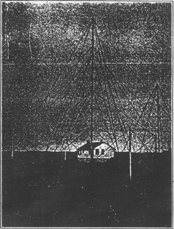
Figure No. 8
Resolution Island 1929
Directing Finding Station showing
Combined Operating and Power House
with Steel Mast Supporting Loop Aerials |
the accuracy of a similar instrument ashore, and with
the important advantage that it is the ship herself who takes the bearings
instead of an operator ashore. The importance of this can readily be
appreciated.
As a result of this there came into being what are
termed radio beacons, which in effect are radio lighthouses, with a range of
about 75 miles.
The first series of Canadian beacons were installed
at Cape Bauld, Belle Isle straits; Cape Ray, Cabot straits; Seal Island, N.S.,
and on light ships located off Heath Point (Anticosti), Sambro, and Lurcher
shoals.
They consisted of converted sets of the spark type
and obtained their power supply from the prime mover of the fog alarm, being
worked during fog only. They were operated through a period of useful
experiment, and, sufficent data and experience having been secured to form
reasonable conclusions, the Department, two years ago, embarked on a regular
scheme of installation of an automatic tube type of transmitter. The apparatus
was developed in conjunction with the Canadian Marconi Company, and now ten sets
are in operation at Lurcher Lightship, Seal island, Cape Whittle, West Point (Anticosti),
Pointe des Monts, Main Ducks, Long Point, South East Shoal, Cove island and
Michipicoten island, with nine more in course of installation.
Our original idea of the beacon was the long distance
fog alarm, but as our experience grew, the conclusion was reached that the
navigator really desired a 75-mile light-house available day and night, 365 days
a year, and the new apparatus is designed to attain this end. The transmitter
is automatic in all respects. It has as a source of power a gasoline driven
electric generator of the automatic start type, and the control of the whole
equipment rests in a master clock. Each beacon is given a
characteristic, whereby it may be identified. In fine weather the clock
automatically starts the engine once an hour and automatically puts the
transmitter on- the air for one minute and off for two, for a period of. five
minutes, when the clock automatically shuts the whole plant down. In foggy or
hazy weather the lightkeeper throws what is called the fog switch and the beacon
then functions automatically one minute on, two off, until the lightkeeper
throws the switch back to fine weather schedule.
 Details of the beacon transmitter may be of interest. Details of the beacon transmitter may be of interest.
Four transmitting tubes are used, each rated at 50
watts output, arranged to work in what is generally called a back to back self
rectifying circuit. The high tension for the anodes of the tubes is obtained
from a 500-cycle alternator driven by a 110-volt d.c. motor. This alternator
supplies current at 110 volts to the primary of a transformer which raises it to
1,500 volts. The secondary of this transformer is centre tapped and its outside
terminals are connected to the anodes of two tubes operating in parallel.
This arrangement gives a note modulated at 1,000
cycles which is distinctive and can be read on a non-oscillating receiver. In
addition it has the advantage of avoiding the necessity of using a thermionic
rectifier or high voltage d.c. generator for supplying the high tension necessary for the tube anodes and the
necessity of providing auxiliary modulating equipment.
|
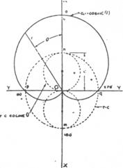
Figure No. 10
Polar Diagram showing Types of Reception
obtained with An Ordinary Aerial and a
Loop Which Combine to Form the
"Heart Shaped" Diagram with One Minimum |
In order to obtain good regulation of the
filament-heating current it is supplied at 60 cycles from a separate small
converter.
A hinged gate at the front of the unit gives access
to the tubes and is equipped with an automatic safety gate switch which
interrupts the a.c. supply and renders the set dead when the gate is opened.
The brains of the equipment rest in a clock
controlled time switch. The clock is a high grade eight day spring driven
movement with balance wheel escapement suitable for use either ashore or afloat.
The usual hands are replaced by a disc which makes a
complete revolution once an hour. This disc carries a series of pins or studs
mounted on its face, which engage two light contacts possessing quick make and
break features, called clock contact No. 1, and clock contact No. 2. No. 1
controls the starting and stopping of the engine-driven generator and No. 2 the
duration of the transmission and silent periods.
Figure No. 14 illustrates the general appearance of
the control clock, which is mounted in a water and dust proof metal case.
The source of power for the beacon transmitter is a
2-k.w., 110-volt d.c. generator, driven by and directly connected to a four
cylinder gasoline engine rated at four horse power. This unit is automatically
started from a 32-volt storage battery when a load equivalent to a 75-watt lamp
is switched on across its output terminals.
|
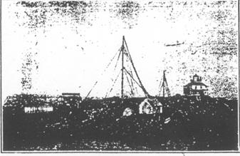
Figure No. 11
Radio Beacon |
This initial load is provided by a 150 ohm resistance
connected in parallel with the energizing solenoid of a 110-volt shunt relay and
is switched on and off by the No. 1 contacts of the control clock.
As soon as the circuit is closed by the No. 1 contact
the engine driven generating unit starts and when it has built up to its full
voltage of 110 volts, which it will do in approximately ten seconds, the shunt
relay will begin to operate to close the remote control contacts on the solenoid
operated starter of the motor alternator. This starter is of the progressive
contact type and is adjusted, by means of an oil filled dashpot, to bring the
motor alternator up to speed in twenty seconds.
The motor which drives the character disc is started
at the same time and through the same operation.
Actual transmission is controlled by the second set
of contacts on the time switch, and these are timed relatively to the No. 1
contacts so that transmission does not begin until one minute and forty-five
seconds after the engine has been started in order to ensure that it will be
running evenly and will drive the motor alternator at uniform speed under load.
The No. 2 contact on the clock energizes a relay to
close or interrupt the primary circuit of the 500-cycle transformer, which
supplies high tension to the anodes of the transmitting tubes. This circuit is
closed for a one minute and fifteen seconds transmission period and then opened
for a one minute and forty-five seconds silent period. This sequence is
transmitted twice at the beginning of each hour day and night during clear
weather and is repeated continuously during fog.
The character disc through a keying relay makes and
breaks the same circuit to form the signals of the beacon characteristic.
When the clear weather hourly operating period of six
minutes is over the clock opens the energizing circuit of the main starting
relay which, in turn, drops out and opens the remote control circuit of the
solenoid operated motor starter. For continuous operating during fog, a single pole
switch. located on the main control panel above the starting relay. is closed,
short circuiting the No. 1 contacts on the clock. This takes the control of
starting and stopping away from the clock and the generating plant will continue
to run so long as the engine is supplied with fuel. The transmission and silent
periods are still controlled by the No. 2 contacts of the clock.
|
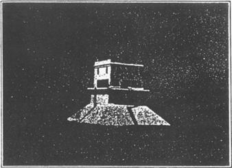
Figure No. 12
Combined Lighthouse, Fog Alarm and
Radio Beacon Station erected on
South East Shoal, Lake Erie,
by the Canadian Government |
In order to draw the attention of the attendant in
case of overload or if the filament of a. transmitting tube should burn out, an
alarm bell operated through an auxiliary relay is provided. This auxiliary relay
is energized from the 110-volt d.c. circuit in series with the overload trip
coil of the circuit breaker and also through a differential relay in the
filament circuit. Of the four filaments, two are connected in each side of the
differential relay and under normal conditions the two sides are balanced and
the relay is inoperative, but if one tube burns out the two sides of the relay
become unbalanced and it will operate to energize the auxiliary relay and
through it close the bell circuit. After the auxiliary relay has been tripped by
the operation of either the overload or the differential relay the alarm bell
will continue to ring until the auxiliary relay is reset by hand.
All beacons are provided with duplicate equipment
throughout, and a transfer panel mounted between the two transmitters permits of
using either engine with either transmitter and either control clock. (See
figure No. 15.)
In connection with radio beacon installations,
methods have been developed for synchronizing transmission of the radio signal
with that either of a local fog horn or a sub-marine oscillator, in order to
provide means for determining the distance intervening between a ship and the
beacon. This is done by observing the time which elapses between the reception
of the radio signal and the sound signal of the fog horn or submarine oscillator
and by a simple calculation, based on the rate of travel of sound in air or
water, as the case may be, a navigator can determine the distance with a fair
degree of accuracy.
LONG DISTANCE COMMUNICATION BY MEANS OF THE
MARCONI SHORT-WAVE BEAM SYSTEM
Canada's pioneer work in the matter of trans-Atlantic
communication did not end with Glace Bay, and it is interesting to note that the
first commercial long distance beam -short-wave radin
service was that established by the Canadian Marconi Co. between their station at
Drummondville, near Montreal, and a station at Bodmin, England, which was put
in commission on October 25th, 1926. Today hundreds of long distance short-wave
stations are in operation in practically every country of the world, and, as a
consequence, one of the biggest problems with which those charged with the
administration of radio are confronted is to fit them all into the radio
spectrum. A station in Montreal interfering with a station in Toronto is a
simple matter to sort out, but a station in the Dutch East Indies interfering
with a station in London which communicates with Montreal is a much more
complicated affair.
|

Figure No. 13
100-200 Watt Radio Beacon Schematic
Diagram of Automatic Controls |
Prior to the advent of the beam in 1926, long
distance communication was usually carried on on long waves of from 8,000 to
20,000 metres, with frequencies of 37,500 to 15,000 cycles, but since that date
there has been a complete revolution in this phase of the art, and while today
there are a few long wave stations left, all new development is along short wave
lines. Canada has two international short-wave circuits, the one to England
above mentioned, and one to Australia opened by the Canadian Marconi Company in
June 1928. The frequencies used on the British circuit are 18,180 kilocycles day
and 9,330 kilo-cycles night, and on the Australian circuit the same frequency is
used both day and night, but at night signals are shot around the world the
other way. In addition there is an experimental short-wave voice telephone
circuit between Montreal and London which we look forward to seeing in
commercial operation in the not too distant future.
Those who listened in on the speeches given at the
inaugural session of the Disarmament Conference had an opportunity of testing
the quality of this particular short-wave circuit, over which the signals were
brought to Montreal, where they were put on the telephone wires and distributed
to the Canadian broadcasting stations from coast to coast.
Telephone communication with Australia has also
proved entirely practicable, but it is doubtful if there is sufficient
commercial demand for such a circuit to warrant placing it in operation in the
immediate future.
|
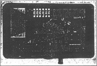
Figure No. 14
Clock Operated Time Switch
which controls the Automatic Transmissions
of the Canadian Government
Radio Beacon Stations |
The Canadian Marconi Company's beam transmitting
station in Canada is situated at Drummondville, thirty miles east of Montreal,
and the receiving station at Yamachiche, twenty-five miles north of
Drummondville. These stations are linked up by land line to the central office
of the Company at Montreal, from which the transmitter is automatically
operated.
The moment the operator in Montreal presses his key
or feeds his message tape into a high speed telegraph instrument, the signals he
is sending are instantaneously recorded at the distant terminal office of the
circuit, whether it be 3,000 miles away, in London or the longer distance to
Melbourne.
Incoming signals from the corresponding stations are
received at Yamachiche, and after being heterodyned to a ver
frequency, amplified, and filtered, are conducted by :dlines, consisting
of open wire lines and cables, to the !ce in Montreal
where they are automatically recorded I are transcribed for delivery to the
addressee.
For convenience in briefly describing the beam system
distinctive features may be divided in the following or parts:
(1) The aerial and reflector.
(2) The aerial feeder system.
(8) The transmitter.
(4) The receiver.
(1) The aerial systems at the transmitting and receiving
stations are identical and are supported on guyed elevated lattice masts, the
exact height depending to some extent on the wavelength used. The usual height is about
150 feet with cross arms at the top measuring 90 feet
from end to end. The design of the masts and aerials is
peculiar to the short-wave beam system and is entirely different from the sign previously used
in commercial radio stations. In ordinary radio station the aerial consists of a
series horizontal wires suspended at a height on a line of masts
interconnected with the transmitting apparatus by a vertical oblique
section. With the beam system, the aerials consist of a number of vertical
conductors forming a wire tain suspended from horizontal
supporting steel cables attached to the ends of the cross arms at the top of the
masts. The aerial system is on one side of the masts facing the distant station and the reflector system similarly
constructed is suspended on the opposite side.
There are usually five masts for each service erected
in straight line and aligned so that the great circle bearing the distant
station is at right angles to the line of the masts. The usual spacing between the masts is 650 feet
making total length of each line of five masts about 3,150 feet. The beam leaves the aerial system at right angles
to the
plane of the masts and follows the shortest track in the direction of the
corresponding station and the station, being in the centre line of the beam,
receives the maximum strength of signal.
Each service usually employs two waves and therefore
aerial systems, one for day and one for night working. It may be interesting to
note here that in the case of England to Australia circuit, only one wave length
is the reflector between them, the transmitter- being
switched from one to the other as conditions require. This simplification was
decided upon following the discovery during preliminary tests of this circuit,
in 1924, that the position and altitude of the sun had an effect upon the
transmission of signals, and that during the morning period the waves travelled
from England to Australia starting in a westerly direction across the Atlantic
and Pacific Oceans, following the great circle along the longest route,
approximately 12,000 miles, but during the evening period they travel in an
easterly direction over Europe and Asia, following the shortest route which is
about 9,000 miles.
Each aerial occupies two bays between the masts and
in radio parlance may be said to consist of a sheet of parallel elements made up
of a number of vertical doublets linked by phasing coils. The aerial wires are spaced about one quarter
wave-length from a screen composed of twice as many reflector' wires. The aerial arrangement is such that the currents fed
into the parallel wires of the aerial are all in phase. Under this condition the
energy radiated from the individual wires cancels out in the plane of the wires,
but adds in the direction at right angles to this plane.
The effect of the reflector is to cut off the back
radiation from the aerial and to strengthen it in front, the total result being
a strong beam of radiation confined almost entirely. to one direction and spread
over an angle determined by the dimensions of the aerial.
The calculated directional effect of aerials of
different widths is indicated below:
Width of aerial in wave lengths: 1 4 20
Approximate horizontal angle within which practically all the energy is confined: 180 deg. 30 deg. 6
deg.
The greatest energy concentration by directional
effect for a given area of aerial, and therefore for a given cost, is obtained
by having equal areas at the transmitter and receiver. Thus an aerial of 20
square wavelengths at the transmitter or the receiver may give a concentration
equal to 200, but if divided into two aerials one at the transmitter-and one at
the receiver, each of 10 square wavelengths, the resulting concentration will be
equal to 10,000.
|
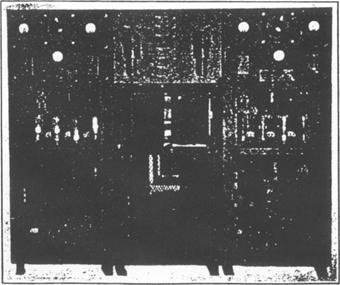
Figure No. 15
Type of Transmitter Installed
at Canadian Stations |
(2) The feeder system by means of which energy
is transferred from the transmitter to the aerial consists of concentric copper
tubes, the outer one of which is earthed and the inner tube insulated from it by
means of a special porcelain insulator. This feeder system is so arranged that
the length of feeder to each individual aerial element is exactly the same,
which ensures that the currents in all the aerial wires are in phase.
(3) The transmitter is specially designed.to
give great stability of wavelength, a point of the utmost importance in dealing
with short waves; 20 k.w. is supplied to the anodes of tubes in the final
amplifier stage, from which ample energy is fed through the feeder system to the
aerial to permit of high speed working.
Stability of wavelength is obtained by means of a
master oscillator which controls the frequency of the succeeding amplifer
stages and also by careful arrangement and screening of the components.
Stability of the emitted wave is further assured by diverting the high tension
supply through resistances during the spacing periods and so keeping a constant
load on the generators.
In order to deal with the high frequencies
encountered in short-wave working, special transmitting tubes are used. These
are oil cooled and operate at high efficiencies.
(4) The receiver is coupled to the reflecting
aerial system by means of a feeder arrangement similar to that employed at the
transmitting station, and consists of nine carefully screened units conveniently
mounted on a vertical rack.
|
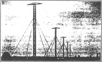
Figure No. 16
Short-Wave Beam Receiving Station
at Yamachiche showing Masts Supporting
Reflector Aerial for Receiving from England |
The signal in passing through the receiver, in
addition to being amplified, has its frequency lowered by being heterodyned to a
suitable value for efficient transmission over landline to the central office.
The receiver has incorporated in it band pass
filters, which allow only certain narrow bands of desired frequencies to pass
through, and the intensity of the signal finally transferred to the landline is
automatically prevented from exceeding a certain maximum value by being passed
through a limiting tube which has its grid so biased as to accomplish this end.
By employing circuits analogous to those extensively
used in carrier current telegraphy for superimposing several communication
channels on one physical wire circuit, each beam aerial can be efficiently
utilized for the simultaneous transmission of telephonic and telegraphic
messages or for the simultaneous transmission of telephonic or telegraphic
messages without there being any mutual interference between these services.
Facsimile transmission can also be employed with the
beam svstem over practically any distance.
It may be interesting to note here that the carrier
current systems of telegraphy now being extensively installed by both the
Canadian Pacific and Canadian National Telegraphs on their long heavily loaded
landlines for greatly increasing their traffic handling capacity employ
apparatus made possible by the use of thermionic tubes, first developed by the
radio industry.
With regard to the relative advantages of the beam as
compared with the older systems of long wave radio communication, the following
may be cited:
1st Less capital expenditure required.
2nd Less electrical power required to operate the
transmitters.
3rd Greater speed of transmission possible. At
present this is limited only by the mechanical limitations of the keying and
recording instruments.
4th Due to the restriction of the radiation to a
narrow beam, to the screening effect of the reflector at the receiving station
and to the large number of wave-bands available, a greater number of services
can be carried on.
5th Due to the screening effect of the receiving
reflector the signal-to-interference ratio is increased, and consequently the
traffic capacity is increased, because the possible sources of interference are
reduced in pro-portion to the narrowness of the arc of reception.
The competition of the beam stations has introduced a
new factor in international communication and as a con-sequence a merger has
been formed in England to unite the British cable and radio telegraph systems
into one.
One advantage enjoyed by the beam system over the
cables is the fact that two beam stations capable of communicating half way
round the world may be built for approximately half a million dollars whereas
the cost of laying a permalloy loaded cable capable of working at similar speed
is many times as great and increases in proportion to the distance separating
the terminal stations.
In this regard it is interesting to note that a cable
of this type laid between New York and the Azores, a distance of 2,328 miles, is
reported to have cost four million dollars.
RADIO BROADCASTING
The extraordinary development of broadcasting is
familiar, but it is not generally known that Canada is also a pioneer in this
phase of the radio art. The Canadian Marconi Company commenced their first
regular weekly broadcasts from their station "XWA" at Montreal in
December, 1920, on a wavelength of 1,100 meters, and they challenge the honour
which Westinghouse, Pittsburgh, claims to hold. In protecting the interests of
the broadcast listener Canada has been prominent. No other country in the world
attempts any such service to broadcast listeners as we endeavour to give, in the
matter of clearing up ship interference. In this Canada led the way by making
treaties with ten countries, as early as 1925, arranging to have their ships
stop the use of any wave in the broadcast band when ships flying their flag were
on this side of the Atlantic, or the Pacific.
|
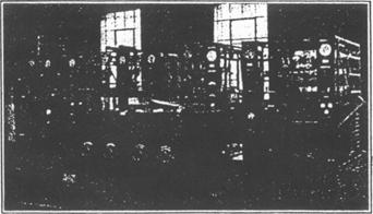
Figure No. 17
Short-Wave Beam Transmitter
at Drummondville, P.Q. |
All spark transmitters on government stations at
points where they could cause interference were scrapped and replaced by tube
sets, and at the International Radio Convention at Washington in 1927, at which
seventy-six administrations were represented, the policy of the Canadian
Government was given international effect. and rules were drawn up making
international the regulations and arrangements which previously had been in
effect in Canada and the United States.
There are today in Canada upwards of half a million
radio receiving sets and sixty-six broadcasting stations. The future of the
latter is still to be decided. A Royal Commission on broadcasting was appointed
to enquire into this matter a year ago, and its report will be dealt with by
Parliament during the coming session.
Whereas many of the original stations employed
transmitters rated at from 50 to 250 watts output, there are now several
stations in Canada equipped with transmitters rated at 5,000 watts.
Our neighbours to the South are employing many
broadcast transmitters rated at 50,000 watts, and transmitters of four times
this power have been successfully operated in experimental tests, so that it is
reasonable to expect to see transmitters employed in Canada of considerably
higher rating than those at present in use.
Improvements have been incorporated in the design )f
amplifying and modulating equipment which now permit ,the carrier wave to be
practically 100 per cent modulated, with the result that the effectiveness of
the equipment s quadrupled as compared with the older type of transmitter which
was capable of being modulated to only 50 per cent.
In order to prevent stations occupying adjacent
frequency channels, which are only 10 kilocycles wide, from deviating from their
allotted frequencies and so interfering with each other, crystal control of the
carrier frequency has :orne into prominence. A piezo
crystal consisting of a. small quartz plate about one inch, square is used to
control a master oscillating circuit. The faces of the crystal are accurately paralleled and ground to a thickness
associated with the frequency of mechanical vibration required. In order to
insure frequency stability the crystal is mounted in a heat insulated chamber,
the temperature of which is held to very close limits by the use of a sensitive
thermostat controlling a heating element.
Tests of this method of control have shown that it is
possible with ordinary supervision on the part of the operating staff to
maintain the carrier frequency well within 100 cycles of the assigned frequency.
When it is recalled that the carrier frequency may be as high as one and one
half million cycles per second, control to within 100 cycles is a truly
remarkable precision.
With broadcasting stations as originally constituted
it was necessary that the programme to he broadcast should originate in a studio
located in the same building as the transmitter. However, by the development of
portable pick-up and amplifying equipment for use with the local telephone
lines, and by improved methods of .compensating the latter to give substantially
uniform transmission of the frequencies involved, the possible separation of the
point of origin of the programme from the transmitter was gradually extended.
The successful application of the thermionic tube to
act as a repeater in long distance telephone communication circuits has had a
marked effect on the extension of the distances over which such lines can be
successfully operated, and in consequence, it is now possible to link up many
widely separated broadcasting stations by means of wire lines, in order-that a
programme of general interest originating at one point may be simultaneously
broadcast.
Two of the outstanding uses to which some form of
thermionic tube has recently been put are in the develop-ment of television and
in the production of sound motion pictures. The sound motion picture art has
progressed with great rapidity during 1929, and the public reaction is one of
increasing acceptance and patronage. The adaptation of radio broadcasting
technique to this newest division of electrical engineering is an interesting
example of scientific evolution and adaptation.
A few years ago the thermiomic tube was of interest
primarily in radio and in landline telephony and telegraphy. Today it is a vital
factor in a dozen industries and is of increasing significance in a score of
others.
Even in this age of wonders the rapid progress made
by radio stands out as phenomenal, and if we pause to consider its future
possibilities, there is no doubt that, intelligently employed, it may become
one of the most potent factors in bringing about mutual understanding among all
peoples and the promotion of an irresistible sentiment in favour of universal
peace.
|